

The useful life expectancy of traditional enterprise network infrastructure is regrettably short. At each one of these upgrades, the switch and cable manufacturers expected you to rip-and-replace your hardware and infrastructure. Each higher bandwidth step and faster network speed introduces disruption in the Local Area Network (LAN). Furthermore, during this same time period legacy switch venders are complicating matters by raising network complexity, day-1 capital cost and year-over-year operational expenses. So, how can you better align real space, energy, heat, noise, radiation, and costs impacts, with your true enterprise bandwidth requirements?
Passive Optical LAN (aka POL or OLAN or POLAN) is a better way to build and operate networks. Optical LAN speeds IT productivity through simplification. It reduces network vulnerability points. It offers flexible design options to right-size capacity and density. Optical LAN is optimized for modern fiber-based network connectivity inside buildings and across campus.
This white paper explains what Passive Optical LAN is, how it works and why it benefits your organization. It will do so by detailing why enterprises are looking to deploy Optical LANs for its:
- Contemporary fiber design versus legacy copper LANs
- Converged connectivity for modern offices, IoT and smart buildings
- Reduction in space and use of less material
- Improved reliability with higher network availability
- Tightened security by reducing points of vulnerability
- Delivery of significant monetary savings
Contemporary fiber-based option to legacy copper LANs
A Passive Optical LAN is a Layer-2 transport medium, built with Passive Optical Network (PON) technology, which provides converged video, data, wireless and voice services over a single strand of fiber to the connected device. Comparing the configurations of a traditional copper-based LAN and a Optical LAN architecture helps to illustrate more clearly the similarities between the two technologies.
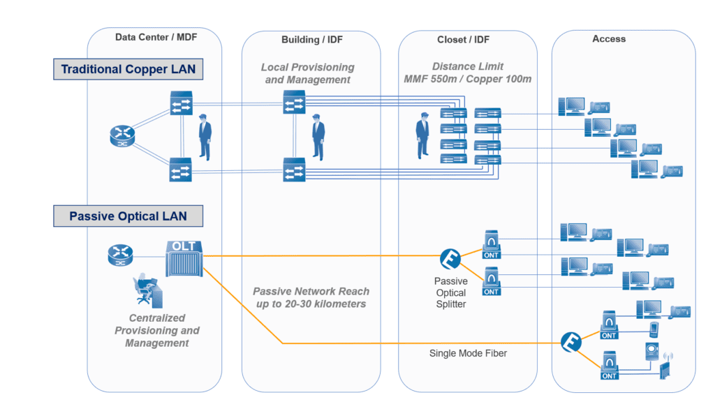
Legacy Copper LAN – In a traditional copper-based LAN, a router in the top-most layer (Core Layer) links to the campus or building aggregation switches (Distribution Layer). The distribution switches connect down to the Access Layer switches in the communications closets. Copper cables extend from the communications closets to the users and end devices.
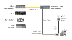
Passive Optical LAN – In an Optical LAN solution, the router is retained in the top-most layer, and the Optical Line Terminal (OLT) serves the same purpose as the campus aggregation switches. The building aggregation switching is accomplished by the 1×32 (or 2×32 for equipment redundancy and fiber route diversity) optical splitter, which is a passive device, so there are no power requirements and little management while being highly reliable. The Optical Network Terminals (ONT) provide connectivity to the users and end devices.
It is important to note that both solutions provide data access via Ethernet connections to the user and devices Therefore, no client or PC reconfiguration is required when upgrading to a PON infrastructure. Enterprises also have the flexibility to deploy an Optical LAN in a fiber forward (e.g. ONT mounted at zone box, wall or desktop) or a closet-based ONT (e.g. fiber-to-the-communications room) topology. A splitter-equipped fiber distribution hub on each floor routes the fiber to the desktop ONTs throughout the building. The closet-based ONT architecture allows for the reuse of existing copper cables between the communications closets and the end-devices connected.
A Passive Optical LAN’s ONT has all the required Layer-2 functionality built in. The Optical LAN provides integrated Ethernet bridging, the VLAN capability required for network segmentation, and user authentication and security filtering. The ONT, which functions much like an Ethernet switch, makes it possible for an enterprise to seamlessly replace an Ethernet-switched LAN.
The primary components for Optical LAN consist of:
- Optical Line Terminal
- Singlemode Fiber Cabling
- Passive Optical Splitters
- Optical Network Terminal
- Management Interface
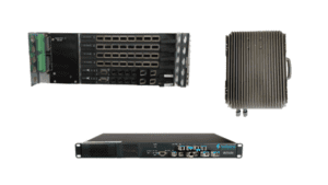
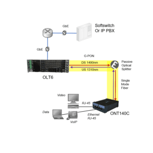
Optical Line Terminal – The OLT is typically located in the building’s main data center and provides aggregation plus distribution of the enterprise network connectivity. A single OLT can be sized to support from 200 Ethernet connections to over 7,000 Ethernet connections from one location. It is the OLT that is connected to the Wide Area Network (WAN) and all internal resource servers through the core router. An OLT can be one rack unit in height (1 ¾ inches) to four rack units high (~ 6 inches) and even with the inclusion of powering equipment and fiber management typically all fits in one telco rack. Today’s OLTs support both Passive Optical Networking service modules that allow XFP selectable ITU-T 984 G-PON 2.5G or ITU-T G.9807/G.987 XGS-PON symmetrical 10G connectivity down to the ONTs.
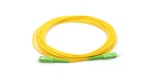
Singlemode Fiber Cabling – SMF is the fiber optic cabling that runs throughout the building’s risers and pathways. It is the SMF that physically connects the OLT, splitters and ONTs. That said, it should be noted that there are options for operating PON over multimode fiber (MMF) and there are closet-based ONTs that can leverage the last 300’ of copper-cabling. There is also the choice of installing composite SMF cabling that includes two copper wires within the cabling jacket for remote powering of the ONTs.
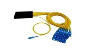
Passive Optical Splitters – Optical splitters provide the point-to-multipoint connectivity between the OLT and the ONTs. The splitters offer flexible mounting in telecom closets, wall enclosures or ceiling enclosures. They offer split ratios from 1:2 up to 1:64 with the most common split ration being 1:32. Optical splitters also provide equipment, fiber and services protection through 2:X redundancy options. They are unmanaged, unpowered and highly reliable.
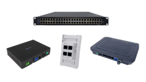
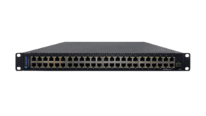
Optical Network Terminal – ONTs enables optical to electrical conversion and Ethernet connectivity for voice, video, data, Wi-Fi and all other digital enterprise services and devices. ONTs are Power over Ethernet (PoE) enabled and subtend other powered devices (e.g. phones, cameras, wireless access points). ONTs themselves can be either locally powered from a nearby AC outlet, or remotely powered from a DC source. ONT mounting can be located above the desk, below the desk or can be nearly flush-mounted in the wall. They can also be mounted in zone boxes, with optional plenum brackets and in raised floors. Finally, there are also options for rack-mounted 48-port Ethernet ONTs that provide an economical one-to-one replacement of traditional closet-based Ethernet switches that can continue to utilize the last 300’ copper cabling drops inside a building.
Management Interface – The management interface (i.e. Element Manager) provides the centralized intelligence and management of the passive optical network elements and subtended powered devices (i.e. powered devices). The PON Manager provides the one console and one screen control to orchestrate consist, repeatable, error-free IT policies and procedures through software defined global profiles. This type of network management meets the goals of Software Defined Networking (SDN). Software definitions enable simplified setup of profiles for ONTs even when thousands are deployed. The IT staff control and visibility goes all the way down to the individual port level. This results in easier diagnostics and troubleshooting, plus reduces errors and administrative costs. The PON Manager is accessed via Client-Server or Web-Brower interfaces.

Converge modern offices, IoT, wireless and smart buildings
Passive Optical LAN can converge all services across a single fiber-based infrastructure, eliminating the need for multiple platforms while providing highly scalable high-speed data services to all users. For example, Optical LAN can connect:
- IP and Analog Voice
- IP and RF Video
- Wireless
- Smart Building and Internet of Things (IoT) Connectivity
IP and Analog Voice — Providing the same services as a legacy switching architecture, VoIP handsets are connected at the ONTs via a standard RJ-45 gigabit Ethernet port. The VoIP service is transported to IP PBX or softswitch as standard IP/Ethernet traffic.
Though not as common, the OLTs and ONTs can also support analog voice, or what is commonly called Plain Old Telephone Service (POTS). In this scenario, the ONT itself contains a Session Initiation Protocol (SIP) to the analog converter that allows the POTS phone to plug into an RJ-11 port on the ONT. As the ONT converts the POTS call to SIP, it is transported over the Optical LAN system in a VoIP format.
The ONTs do support IEEE standards for IEEE 802.3af PoE (15.4 watts at an Ethernet port) and IEEE 802.3at PoE+ (25.6 watts at an Ethernet port) to power the VoIP handsets. regardless of the solution being deployed (VoIP or POTS services), the Optical LAN system provides the necessary network protocols and quality of service (QoS) required in the modern enterprise environment. This allows for VLAN trunking and creating “daisy chained” PCs fed off of the VoIP endpoint with a separate VLAN and QoS settings for each achieved via standards based on IEEE 802.1q and Differentiated Services Code Point (DSCP) mappings that guarantee that the voice calls are clear.
IP and RF Video — Since Passive Optical LAN is a standard transport system, IP video content can be deployed with little effort. As an example, small enterprises are able to encode off-air analog and digital channels, and deliver them in both standard definition and high-definition quality. These video networks are built to support local cached content for video on demand (VoD) and other interactive services. There are even options for local content insertion (e.g., facility news, company news and training). This is accomplished over the Optical LAN equipment, since the video is once again transported in an IP/Ethernet format. As the Optical LAN system leverages Internet Group Management Protocol (IGMP) multicast delivery mechanisms, it is a highly efficient means to deliver video on the network. IGMP multicasting takes place across the OLT and ONTs so as to ensure that only a single copy of the unique IP video stream is efficiently sent across the network, optimizing bandwidth. This same architecture can support enterprise-centric IP video, such as video conferencing (VTC), telepresence conferencing, telepresence robots and video surveillance.
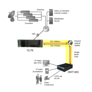
Identical to voice services on the Passive Optical LAN, strict QoS preserves the video content and priority in the network. This is especially critical in video conferencing (VTC) and in telepresence applications. The video is delivered through rate limiting (shaping), queue management (buffering) and scheduling (policing) mechanisms. Bandwidth rate limiting is set by provisioning the sustained data rate levels and burst or peak rate for proper traffic shaping. Finally, the OLT and ONT queue (buffers) and scheduling (policing) smooths any bursty traffic. All of the above together builds your service level agreements (SLAs) that ensure that the IP video quality is high and the user experience is superior.
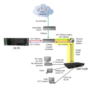
If there is RF video, Passive Optical LAN provides video overlay service in compliance with ITU-T G.984. The RF video is carried on the system using a third wavelength (1550 nm). The video signal format delivered to the customer is defined by SCTE standards. From the ONT, a standard 750-ohm coaxial interface supports 54–900 MHz CATv channel content. Since this is accomplished over a separate wavelength, the RF video network equipment is not aware of the Optical LAN presence. With the centralized management of the Optical LAN, the coaxial output can be tuned to match the signal levels required for the customers remotely and allow for remote balancing of the network.
Wireless — Passive Optical LAN can also be used to backhaul wireless access points traffic. It can do so in two architectures. First, there is the stand-alone static Wi-Fi architecture with no robust controller functionality. In this scenario, Optical LAN can provide the benefits of lower equipment cost, reduced energy and collapsed cabling infrastructure. There are also wireless access point (WAP) features and functionality integration that can be accomplished with POL via the centralized management platform. POL provides a greater system reach for improved performance and coverage for Wi-Fi service. As POL interoperates with established Wi-Fi vendors (e.g. Cisco, Meraki, Ruckus, Aruba, Meru, etc…) it allows for Wi-Fi controller functionality to be provided by best of breed Wi-Fi manufactures without limiting the customer’s options. The controller functionality adds dynamic provisioning, interference correction, load balancing and coverage optimization as is required in a true enterprise deployment.
There are also synergies between Passive Optical LAN, Distributed Antenna Systems (DAS), Small Cell, future 5G cellular readiness and fiber optic cabling. To be clear, the cellular traffic does not traverse the POL equipment, but it can leverage the same fiber infrastructure that POL utilizes. Alone, indoor enterprise cellular networks have a challenging return-on-investment analysis – it is relatively expensive, it only does one thing and the end customers think they should not have to pay for it. POL has an excellent ROI that can justify the deployment of indoor cellular over existing fiber plant inside buildings and across a campus. One thing is certain, these next-generation enterprise cellular network solutions are not going to be supported on, nor their traffic backhauled over, copper-based CATx cabling. Thus, investments in fiber optic cabling is protected even relative to future demands of indoor enterprise cellular networks advancements.
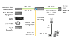
Note: DAS does not travel over OLAN, but leverages same fiber-based infrastructure
It should be noted that the ONTs do support IEEE standards for 802.3af PoE, 802.3at PoE+, and 802.3bt 4PPoE to power the Wi-Fi WAPs. These ONTs provide Powered Device (PD) management, monitoring and configuration using Link Layer Discovery Protocol (LLDP) too. Thus, the ONT detects the actual power requirements of a PD and then adjust the power allocation for that PoE port. There are also mechanisms for providing reports on power consumption so that IT managers may adjust deployment configurations to low-power modes for devices like WAPs and IP phones alike.
Smart/Intelligent Buildings and IoT — Today there is a recognized need to design and build an IT network infrastructure that supports thousands of digital services and connectivity. That same LAN also needs to have the flexibility to expand as thousands of additional gigabit Ethernet connections are added over time as the sheer number of digital devices grows exponentially. This is the same problem statement faced IT professionals around the world as they prepare to support the network demands of smart intelligent buildings and the inevitable impact of the IoT. In a traditional IT network design, this rapid connection growth mean racking and stacking Ethernet switches in telecommunication rooms and running point-to-point copper cabling 100 meters to every connected device. Every time you added the complexity of more electronic switches and copper cables you negatively impact energy, thermals, reliability, security and especially environmental green programs. This is not a sustainable business nor sustainable green approach.
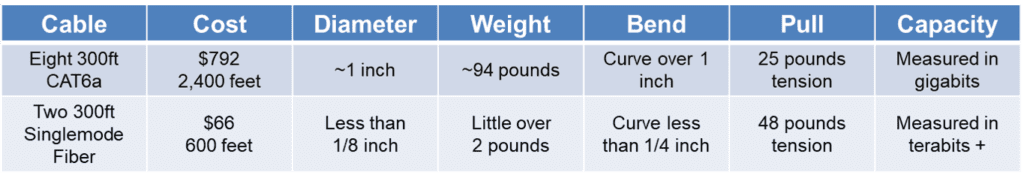
Passive Optical LAN is ideal handle the digital transformation of enterprise business and their buildings. POL network design ensures IT professionals a gracefully and cost effectively means to grow their network connectivity in response to smart building IoT demand by leveraging the Optical LAN system and cabling superior capacity. POL relies on SMF cabling from the main data center through the cable risers, through the horizontal pathways and as close to the digital devices as possible. SMF cable bandwidth is tremendous and is measured in terabits today – far greater than copper cables measured capacity in the gigabits. With this inherent capacity, SMF lifespan is expected to exceed 25 years whereas copper cables historically have been ripped and replace every 5-7 years. Similarly, the Optical LAN system and passive optical splitters already provide a graceful migration to 10G, 40G and 100G capacity with no conflicts. Optical LAN has greater gigabit Ethernet density (in smaller footprint) and scalability to support thousands future smart intelligent building (e.g. IoT). Finally, POL has centralized intelligence and management to manage the thousands of IoT connected devices in more M2M and plug-n-play manner.
Occupy less space and using less material
Cutting back on floor, rack and closet space is also extremely important to organizations looking to save. Reduction in floor space lowers operating expenses by reducing overhead costs, such as fire safety, security and HVAC. In addition, the smaller footprint associated with Optical LAN technology enables contributes to healthy, green and sustainable with POL’s outstanding cradle-to-grave lifecycle analysis.
A typical copper-based LAN serving up to 2,016 users requires 90 rack units of space. Active Ethernet LAN switches require one full rack for the switches and two additional racks for terminating the large bundles of copper cables associated with the switches. The total solution would require a total of 18 seven-foot-tall equipment racks. Comparatively, an Optical LAN serves up to 7,700 users. Due to the OLT’s 90% greater density, this solution requires only one equipment rack and a total of nine rack units within the rack.
Additionally, a Passive Optical LAN requires fewer communications closets and, in some cases, eliminates them altogether. As a result, a business can recover physical space and cut expenses. The SMF cabling in the Optical LAN can reach up to 30 kilometers. This all enables an enterprise to:
- Reduce or eliminate repeaters, switches and communications closets
- Deploy an OLT in a single central location
- Install a future-proof Infrastructure
Improve reliability with higher network availability
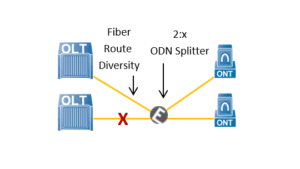
Passive Optical LANs provides enterprise LANs with superior stability, high availability and industry-leading network uptime. This is accomplished with carrier-class componentry, equipment redundancy, dual homing to wide area network, route diversity in fiber cabling infrastructure and redundant OLTs in geographically dispersed locations.
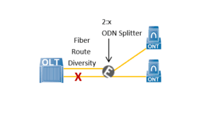
For example, a single OLT can be equipped with a redundant PON port or PON card serving one ONT with two paths across a redundant optical plant. This PON equipment-level redundancy, from one OLT, is a means to provide fiber route diversity using the FSAN ITU standard Type-B PON redundancy option. Type-B PON redundancy is a purely passive solution, defined in principle by FSAN ITU standards, and is contingent on deploying 2:x Passive Optical splitters. These highly reliable 2:x optical splitters provide both protection, redundancy and splitting functions in the optical plant. CIOs and IT pros have a great amount of flexibility as to where these splitters can be placed in their optical plant infrastructure. For example, the 2:x Passive Optical splitters can either be positioned for centralized (e.g. near the data center) or distributed (e.g. far from the data center) architectures. These 2:x passive optical splitters support a variety of split ratios, including 2:8, 2:16 and 2:32, dependent on the type and number of ONTs being subtended. They can be sourced from major Layer-1 optics manufacturers.
Even better, two OLTs at geographically dispersed locations can also be configured to serve one ONT with two paths across a redundant optical plant. Because of this, Type-B PON redundancy provides options for fiber route diversity to different PON ports in the same OLT, different PON cards in the same OLT, and different OLTs in geographically dispersed locations. The use of redundant OLTs in two locations represents the pinnacle of reliability being 99.9999%, as six-nines network availability is the culmination of all redundancy options, including dual homing routers, equipment redundancy and Type-B PON redundancy with fiber route diversity and geographically dispersed OLTs.
Tighten security by reducing points of vulnerability
Passive Optical LAN eliminates network security gaps, which shrinks the network attack surface, and is ideal for Zero Trust initiatives, because of its:
- Secure fiber cabling
- Small attack surface
- Less human touch
Secure fiber cabling – The fiber cabling can make strong contributions to overall security since it is more secure than copper cabling. Fiber is not susceptible to interference nor does it introduce interference. With fiber you have no cross-talk, no EMI, no RFI and no EMP. The opposite is true of copper cabling, which allows radiate emissions that can be eavesdropped without physical access. You cannot “listen to” fiber from any distance, and one would need to physically access fiber to gain entry to fiber-based communications. Physically tapping fiber is tremendously difficult, taking into consideration the expertise and equipment that would be needed. In the end, PON uses a stateful protocols that will detect all abnormal, rogue and intrusion events, so the physical tapping event will be thwarted.
Small attack surface – Passive Optical LAN design significantly shrinks the network attack surface by eliminating IP addresses, and management interfaces, both of which are used by bad actors for malicious intent to breach networks. Optical LAN does this by only having a single management address (one IP address) for up to 8,000 Ethernet ports. In a typical environment that would be around 350 traditional switches to manage that many ports. Each one of those 350 switches have an IP address and a management interface. An Optical LAN only has a single IP address to manage all 8000 Ethernet ports. No ONT has an IP address for management and has no management interfaces on it at all. All management is done via in-band management overhead channels with no access from the data plane. Thus, POL provides a 350:1 reduction in attack surface.
Less human touch – Furthermore, Passive Optical LAN requires less human touch to operate – typically 6:1 less. With centralized intelligence and management, Optical LAN improves IT staff efficiencies with automation by using PON manager’s global profiles that increases the speed of LAN installations, configurations, monitoring, troubleshooting and MACs. With the PON manager’s global profile automation, human touch and human error is reduced which directly lowers security risks.
This is why Passive Optical LAN is an ideal architecture for networks following Zero Trust model because it follows the principals of granular access and least privileges, policy enforcement point, shrinking implicit trust zone, secure network access controls, strong monitoring human access and micro-segmentation.
Deliver significant monetary savings
When purchasing new network infrastructure, it is important to look at both the near-term and long-term expenses. Today’s enterprises require solutions that not only lower initial capital expenses but also reduce the total cost of ownership (TCO) for the network. Passive Optical LAN saves money in many ways, such as:
- Day-1 CapEx savings
- Year-over-year OpEx savings
- Less disruptive network upgrades
- Fewer technology refreshes – investment protection
Capital savings – Passive Optical LAN technology enables the enterprise to significantly reduce the cabling infrastructure costs from the data center to the user by significantly reducing the number of cable runs. The result is a decrease in overall operational costs and network complexity. Also, by converging modern offices, IoT, wireless and smart buildings connectivity onto one fiber-based infrastructure, monies can be saved. This integrated approach provides the ability to connect building automation systems, security cameras and building sensors all on the same infrastructure, thereby removing the requirement and expense of separate transport systems across the campus for each technology.
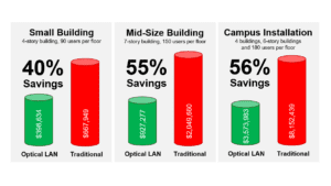
Association for Passive Optical LAN (APOLAN) Technology Committee recently published the results of a cost comparison between POL and legacy switch. Their modeling details savings from 40-56% for POL based on three differently sized deployment scenarios and validates the CapEx saving potential of POL.
Year over year operational savings – Again, with the centralized intelligence and management, Optical LAN improves IT staff efficiencies with automation by using PON manager’s global profiles. Additionally, the elimination of expensive switch hardware lowers drastically lowers provisioning cost, annual maintenance and software licensing fees.
Less disruptive network upgrades – Optical LAN is perfect for new “greenfield” installations, however sometimes customers already have a network in place that they would like to upgrade or refresh. For these “brownfield” installations an ONT with 48-ports of Ethernet can be used to gain all the benefits of an Optical LAN while reusing the existing CATx cabling and powering. These 48-port ONTs are rack mountable, one rack unit high, deliver Power over Ethernet across all ports and exactly match the form-factor of a legacy workgroup switch. They support XGS-PON symmetrical 10 Gbps downstream, and 10 Gbps upstream transmission, so there is plenty of bandwidth.
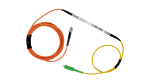
Another hurdle for brownfield projects is existing multimode fiber (MMF) cabling. Despite MMF bandwidth and distance limitations, it may be uneconomical to remove an existing MMF network to replace with SMF cabling. This is often the case with legacy fiber to the desk applications or campus networks that use MMF between buildings. For these instances, SMF to MMF modal adapter jumper cable can be used to connect using PON between optical splitter and ONT. This design enables cost-effective re-use of existing MMF infrastructure inside buildings, and across extended campuses, while gaining all the benefits of Passive Optical LAN.
Fewer technology refreshes – Compared to copper cabling, SMF is smaller, lighter and stronger with a better bend radius and longer reach. It is less susceptible to interference, has faster connector solutions and a longer life, and is more secure and less expensive. Furthermore, fiber cabling also has higher bandwidth capacity, with upper thresholds that are only limited by today’s technology. That means that the current generation OLTs, optical splitters and SMF cabling will not need replacing when the time comes to upgrade the network to next-generation Passive Optical Networking technology in support of 10, 40 and 100 gigabit speeds.
Passive Optical LAN can use Gigabit-PON, or G-PON, which provides the capacity of 2.5 Gbps in the downstream direction and 1.2 in the upstream direction, or there is XGS-PON with symmetrical 10 Gbps downstream, and 10 Gbps upstream transmission. There is also the option for adding multiwavelengths of XGS-PON symmetrical 10G. All the above, whether 2.5G, 10G and 40G have no wavelength conflicts and can be deployed over today’s SMF cabling, optical splitters, fiber management enclosures and powering infrastructure.
Passive Optical LAN Is A Better Way To Build and Operate Networks
Passive Optical LAN can connect any network design, cable, service and endpoint. It economically scales bandwidth capacity, and number of connected devices, with true network needs. Optical LAN breaks traditional network barriers for connecting modern smart buildings and IoT. It offers faster installs with automated connectivity of users, devices, and services. Optical LAN is software defined networking technology that helps IT staff work more efficiently. POL increases speed to provision, monitor, troubleshoot and perform moves-adds-changes. It reduced human touch with consistent policies, improves reliability and security. With Optical LAN, the IT pros, architects, consultants and engineers now have the tools to build enterprise local area networks (LAN) flexibly to support current network speeds and scale up to 10 gigabits of symmetrical connectivity. It allows LANs to be more efficiently designed by minimizing IT infrastructure footprint, power, and costs, compared to legacy copper-based networks. It offers improved flexibility in LAN architecture, and a graceful migration to future network demands. Optical LAN is a wise investment with the least disruptive path to future technologies, including wireless.